 |
|||||||
 |
|||||||
SERVICE TIPS REGARDING THE SL1200 MK2,3,5 PITCH CONTROL CIRCUITS
Having recently serviced a 1200 for an unusual pitch control problem, I
decided to produce a checklist that may help others.
You should have an
analog multi meter available.
Problem #1. Speed OK with Quartz Lock on. The turntable would
work fine for about 30-45 minutes. Then, with the pitch control at -8%, the
platter would start to jerk about 2 times per revolution. as time went on the
range of the pitch control was shifting in the faster direction. In other
words, looking at the platter dots, the +3.3% dots did not freeze until the
control was at the +6% setting. This was tracked down to D301. It was hard to
find this fault because it was heat and time related. If you left the covers
off, it would never fail. it had to be completely buttoned up to hold the heat
in. IC 201 is a major source of heat inside the 1200. I found if I put a
heatsink on IC201 I could also "fix" the problem. This amost had me replacing
IC 201, but the fact that the deck would work fine in the quartz locked (green
lamp on) setting, rules out IC 201. This tells you that the trouble is in the
pitch control circuit. I used a heat gun to carefully heat areas of the board
close to IC301 and that is how I found D301. From a cold start, I could warm it
up and the deck would immediately fail, then cool it by touching with my finger
and the deck would stablize. Replaced the diode and the deck runs fine now.
The way I was able to observe failure with the platter removed was this
way: Keep the pitch control at -8%. Place your DC voltmeter, one lead on
ground, the other lead on pin 6 of IC301. This will read steady something like
4V; but when the circuit begins to fail, you will see the meter pulse upwards
torwards 5V about 2 times a second. If D301 measures greater than 5V with
quartz lock off, It should be replaced. Some also change R307 from 2,7k TO
10kohm, this is probably a good idea as well, but alone may not be a long term
solution to the stability problem should the zener keep drifting higher.
Synopsis We beleive this is related to the quartz switch CD4011B.
This CMOS circuit when operated from 5V has a VIH min of 3.5V. That means that
the waveforms must reach 3.5 for the IC to switch properly. IC201 waveform is
3.8V according to the schematic. It should be easy to see what might happen if
the operating voltage now was, say 5.4V. VIH will be higher as well and the
CD4011 becomes unstable.
So why did the set work ok on quartz lock? The
reason the set worked ok in the quartz locked position is that when the green
LED is on, it too is connected to D301 through a 180 ohm resistor. This added a
load on the 5V zener, bringing the Zener voltage back down to 5V. It might be
better to change D301 to 4.7V in order to lower VIH and improve the stability
of the CD4011.
Problem #2 Speed OK with Quartz Lock off. With Quarz Lock on, after a few minutes, green lamp begins to flash on and off randomly and speed goes haywire. This turns out to usually be a bad pitch slider internal switch contact. But the best way to trouble shoot is the following. Find the pitch control connector on the main board. Connect pins 6 and 7 together. If the problem goes away, it is the the slider. if the problem remains. measure the voltage at pin 13. If it shows to be about 2.5 volts then the LED is ok. If it varies between 2.5 and 0, the LED is shorting out and is defective. Measure voltage at D301, it should be 5.1 volts. If it varies between 5.1 and 0, D301 is shorting out. If it is greater than 5V the zener is open. For all you modifiers out there, this is one area that could use some attention. the 5V zener could be better replaced with a 78L05 regulator.
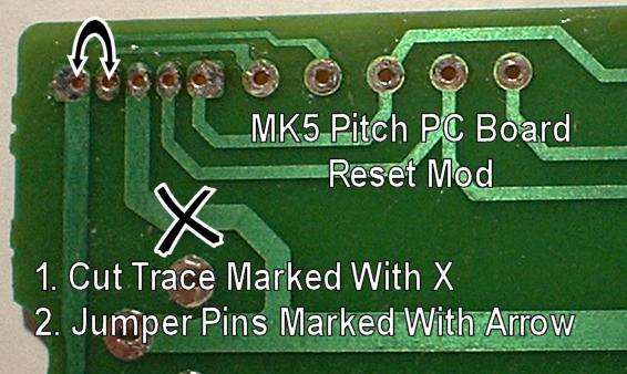
Problem #3 On MK5 Models, the platter speed jitters as you engage and disengage the reset button. Oddly enough, this is normal on most MK5's. MK3 and early MK5's did not have this issue. The original reset switches had a different set of contacts that would prevent this from happening. But in the final analysis, this appears to be an error wholly Panasonic's fault. They are messing with a circuit area that does not need to be messed with. Here is the fix:
1. If you have the board out, or don't mind removing it, just move the brown wire over one to the other hole marked BRN, right next to RED.
2. If you don't want to remove the board, just follow the 2 steps shown below in the graphic.
On MK6, the same problem is present, but the board is different. in the bottom half of the board, cut the trace as shown and run a jumper as shown.
Now the reset will operate smoothly without any platter jitter.
Problem #4 Table functions work, but platter won't sit still when stopped, but instead wiggles back an forth. This was traced to C214 in the brake circuit.


Replacing the Pitch Control LED
All LED's have polarity, which means
they only go in one way. They will not work if installed backwards, and you can
cause damage to them if installed backwards. The long lead is the Anode, the
short lead is the Cathode.
On the pitch circuit board, you will see a
schematic drawing of a diode. The proper relationship is as shown. The best
looking LED's are diffused. Waterclear LED's are very brite. Green is the least
efficient color. Blue for example, is 7 time brighter for the same current. I
like to reduce the current when switching to blue. You can do that by changing
R305. you can find R305 right near the pitch wire plug on the main motor board.
For Blue, a 2K resistor is best.

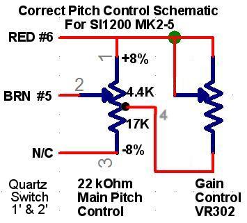
Pitch Control Actual Schematic.
If you look at the standard schemtatics, you quickly realize that they
are all wrong in the way they show the pitch control and the gain control. What
is missing from these schematics is the fact that there is a center tap on the
main pitch control resistor. And it is that tap that connects to the gain
control. The correct schematic is shown below. Take notice that the tap is in
the mechanical center, but it is not the resistive center.
Quartz lock OK, intermittent when using pitch control , sometimes working, sometimes not responding, just standing still
First, place ohmeter on brown pitch lead and confirm smooth continuous resistance from 0 to 10K as you move the pitch control. Next, place ohmeter on pin 2 of pitch integrated circuit and confirm resistance varies when you move the pitch control. Next, using frequency counter, confirm frequency at test point #11. This should be adjustable with the VR301. In this case it was not changing. just drifting around 260Khz. What I found was if I flexed the PC board, the correct reading 262.08Khz would come and go. So this tell me we have a bad connection somewhere. Flipping the board over and inspecting the solder connections I could see that one lead of R303 was not visible through the factory solder joint. Sure enough, I was able to lift up one side of R303 from the board. It was never soldered, ever, right from the factory! Removed the old solder, pushed R303 all the way through the board and resoldered it. Problem resolved. It is interesting to note that someone had been in this deck before and there were new solder joints on every Integrated Circuit. Must have been quite a let down to do all that work and still not solve the problem.